Download Service Repair Manual For Bomag BW 211 D-4 / PD-4 & BW 213 D-4 / PD-4 Single Drum Roller.
Publication No. 00891149 02/2008
This Service Manual offers all the Service and Repair Information for Bomag BW 211 D-4 / PD-4 & BW 213 D-4 / PD-4 Single Drum Roller. With this in-depth & highly detailed manual you will be able to work on your vehicle with the absolute best resources available, which will not only save you money in repair bills but will also help you to look after your business. The information on this manual covered everything you need to know when you want to repair or service Bomag BW 211 D-4 / PD-4 & BW 213 D-4 / PD-4 Single Drum Roller.
Models Covered:
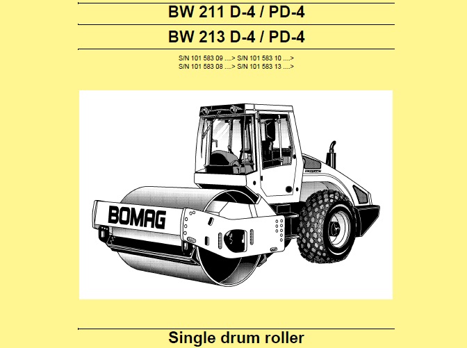
BW 211 D-4 / PD-4
BW 213 D-4 / PD-4
S/N 101 583 09 ….> S/N 101 583 10 ….>
S/N 101 583 08 ….> S/N 101 583 13 ….>
This manual is INSTANT DOWNLOAD. It means no shipping cost or waiting for getting a CD package for several days. you will receive this manual today via instant download on completion of payment via our secure payment processor.
Manual Contents:
General 7
1.1 Introduction 8
1.2 Safety regulations 9
1.3 General repair instructions 14
1.4 Tightening torques 26 Maintenance 31
2.1 General notes on maintenance 32
2.2 Table of fuels and lubricants 34
2.3 Running-in instructions 35
2.4 Maintenance chart 36 Technical data 39
3.1 Technical data 40 Connection overview 47
4.1 Connection overview 48 Tests and adjustments 51
5.1 Special tools, tests and adjustments 52
5.2 Checking the rotation speeds 56
5.3 Checking / adjusting the neutral positions of the travel pump 58
5.4 Pressure tests in the travel circuit 60
5.5 Checking / adjusting the vibrator shaft speeds 62
5.6 Pressure measurements in the vibration circuit 63
5.7 Check the leakage rate of the vibration motor 64
5.8 Pressure test in steering circuit 65 Flushing and bleeding 67
6.1 Special tools for flushing 68
6.2 Flushing – general 73
6.3 Flushing schematic travel circuit (distribution travel pump) 75
6.4 Flushing the travel circuit (travel pump distribution) 77
6.5 Flushing schematic travel circuit (distribution axle motor) 83
6.6 Flushing the travel circuit (axle motor distribution) 88
6.7 Flushing schematic for vibration drive 93
6.8 Flushing the vibration circuit 94
6.9 Bleeding the travel circuit 98
6.10 Bleeding the vibration circuit 100 Fundamental electrics 103
7.1 Understanding circuit diagrams 104
7.2 Terminal designations 109
7.3 Current and voltage 113
7.4 CAN-Bus 116
7.5 Resistance 118
7.6 Series / parallel connection 120
7.7 Ohm’s law 122
7.8 Electrical energy 122
7.9 Formula diagram 123
7.10 Metrology 124
7.11 Diodes, relays, fuses 127
7.12 Batteries 130
7.13 Three-phase generator 133
7.14 Electric starter 141
7.15 Telemecanique switch 144
7.16 Inductive proximity switches 147
7.17 Angle sensors 148
7.18 Plug connectors 150
7.19 Deutsch plug, series DT and DTM 150
7.20 Plugs and terminals in spring clamping technology 157
7.21 Electric modules 160 Special tools, electrics 161
8.1 Special tools, electrics 162 Electronic modules 171
9.1 BEM, BOMAG Evib-meter 173
9.2 Electrics module A68 234
9.3 Electric module K04 242
9.4 Heating/air conditioning control 246 Speedometer Module 253
10.1 Speedometer module 254 Service Training 257
11.1 Service Training 259 Engine 321
12.1 Diesel engine 322
12.2 Fuel filter and check valve 330
12.3 Check, clean the water separator 333
12.4 Change the fuel pre-filter cartridge 333
12.5 Change the fuel filter cartridge 334
12.6 Oil pressure switch and low oil pressure circuitry 335
12.7 Changing engine oil and oil filter cartridges 336
12.8 Coolant temperature switch 338
12.9 Disassembling and assembling the coolant temperature switch 339
12.10 Removing and installing the thermostat 340
12.11 Checking the thermostat in disassembled state 341
12.12 Change the coolant 342
12.13 Checking the anti-freeze concentration 343
12.14 Three-phase generator 344
12.15 Checking / replacing the ribbed V-belt 345
12.16 Boost fuel solenoid valve 347
12.17 Engine shut-down solenoid 348
12.18 Air filter, differential pressure switch 349
12.19 Combustion air filter service 350
12.20 Heating flange on engine 352
12.21 Checking the heating flange control 355
12.22 Electric throttle control 356
12.23 Crankcase – disassembling and assembling the ventilation valve 357
12.24 Disassembling and assembling the starter 359
12.25 Engine monitoring 360
12.26 Adjusting the valve clearance 364
12.27 Adjusting the control piston play 366
12.28 Checking the compression 367
12.29 Engine 369
12.30 Special tools, Deutz engine (TCD 2013 2V) 371 Air conditioning system 391
13.1 Physical basics 392
13.2 Refrigerant R134a 395
13.3 Compressor oil / refrigeration oil 396
13.4 Working principle of the air conditioning system 397
13.5 Monitoring devices 397
13.6 Description of components 398
13.7 Checking the compressor oil level 404
13.8 Checking the magnetic clutch 405
13.9 Inspection and maintenance work 406
13.10 Checking, replacing the refrigerant compressor V-belt 406
13.11 Service the air conditioning 407
13.12 Drying and evacuation 410
13.13 Emptying in case of repair 410
13.14 Leak test 411
13.15 Filling instructions 412
13.16 Trouble shooting in refrigerant circuit, basic principles 415
13.17 Trouble shooting, refrigerant circuit diagram 419
13.18 Trouble shooting procedure 420
13.19 Steam table for R134a 430 Replacing the cab window panes 435
14.1 Assembly of window panes 436
14.2 Special tools 437
14.3 Auxiliary materials 438
14.4 Removing and installing the window pane 440 Drum 445
15.1 Special tools, drum, single drum rollers 446
15.2 Repair overview for drum 448
15.3 Removing and installing the drum 455
15.4 Repairing the drum 461
15.5 Dismantling, assembling the change-over weights 494
15.6 Changing the rubber buffers and adjusting the pretension 497 Oscillating articulated joint 501
16.1 Special tools, oscillating articulated joint (BW177 to BW 216) 502
16.2 Repair overview oscillating articulated joint 504
16.3 Removing and installing the oscillating articulated joint 508
16.4 Dismantling the oscillating articulated joint 510
16.5 Assembling the oscillating articulated joint 515 Suppliers documentation 525
17.1 Travel pump 527
17.2 Vibration pump 617
17.3 Drum drive 655
17.4 Vibration motor 705
17.5 Axle drive motor 729
17.6 Axle 811 Circuit diagrams 933
18.1 Hydraulic diagram 581 202 03 935
18.2 Wiring diagram 582 702 09 939
18.3 Wiring diagram 582 702 29 975
18.4 Wiring diagram 582 702 41 1009
Total Pages: 1046
This manual can be used by anyone from a first time owner/amateur to a professional technician. Even the most novice mechanic can also easily follow the step-by-step guides which are made simple by the illustrations and drawings. Keep this manual handy and use it often. Performing routine, preventive maintenance will save you time & money by helping to prevent premature failure and unnecessary repairs.
Your will receive a download link in no time after your payment is completed successfully. So please make sure your email address is correct. Don’t Forget to Check Spam / Junk if can’t find the new message in your email inbox immediately.
File Format: PDF
Compatible: All Versions of Windows & Mac
Language: English